State Medicaid agencies have spent the past decade modernizing technology. Their next challenge will be governing an ecosystem that never stops changing.
Federal mandates continue to evolve. Modular architectures mean every policy change can affect multiple vendors, systems, integrations, and testing efforts simultaneously. At the same time, CMS continues shifting toward outcomes-based certification that emphasizes measurable evidence over documentation.
While modernization for agency leaders was once measured by system replacement, it is now measured by the ability to continuously adapt while maintaining compliance, accountability, and confidence across an increasingly complex ecosystem.
Looking ahead, the next phase of Medicaid modernization will be defined by governing continuous change.
Modernization Has Changed the Nature of Risk
Technology risk has largely been replaced by governance risk. Today’s Medicaid enterprise environment consists of:
Multiple implementation partners
Modular procurements
Cloud services
AI-enabled capabilities
Interoperability initiatives
Continuously evolving CMS guidance
None of these are inherently problematic. However, the challenge is coordinating them while maintaining a defensible record of every policy decision, requirement, approval, implementation, validation, and outcome.
Today, modernization is less about replacing systems and more about managing change across a living ecosystem.
Continuous Policy Change Is the New Normal
Federal and state Medicaid programs have always evolved. What’s different today is the pace of change:
Community engagement initiatives
Work requirements
Interoperability mandates
FHIR implementation
Eligibility policy updates
Outcomes-Based Certification
Each initiative introduces new requirements that ripple across multiple systems, implementation partners, testing teams, and stakeholders.
How do agencies respond to continual federal policy changes without disrupting delivery? How can they coordinate dozens of vendors while maintaining accountability? How do they demonstrate compliance continuously instead of preparing for certification events?
Technology like Modern Medicaid Enterprise Systems can support evolving changes to policy without disrupting delivery. They were designed to accommodate change. But can organizations implement those changes safely while maintaining confidence in every decision, requirement, approval, and outcome?
How can they coordinate dozens of vendors while maintaining accountability? How do they demonstrate compliance continuously instead of preparing for certification events?
For agency leadership, continuous change is becoming the operating model rather than the exception.
Modular Delivery Requires State-Owned Governance
Modular delivery has become the foundation of Medicaid modernization. States gain flexibility by independently procuring and replacing capabilities over time rather than relying on one monolithic platform.
But modularity also changes accountability. System integrators change and contracts end. Technology evolves, but the state’s business requirements do not. That means agencies cannot outsource ownership of their requirements. State agencies remain accountable for the policies they implement, the outcomes they deliver, and the evidence required to demonstrate compliance.
Organizations that are well prepared for continuous modernization maintain ownership of:
Modernization succeeds when the state remains the steward of its own program, regardless of who builds individual modules.
Evidence Is Becoming More Valuable Than Documentation
Another distinction becoming increasingly visible is how CMS evaluates modernization.
Streamlined Modular Certification and the continued evolution toward Outcomes-Based Certification emphasize measurable outcomes supported by evidence rather than large collections of documentation. Required certification artifacts have been reduced, placing greater emphasis on demonstrating that requirements were implemented, verified, and validated.
This represents an important change in mindset. Preparing documentation before certification events is no longer enough. Leadership teams need confidence that evidence already exists, including every:
Policy decision.
Requirement.
Implementation.
Approval.
Test.
Outcome.
Certification becomes less about producing documents and more about demonstrating a continuously maintained chain of accountability.
Governing Continuous Change
Governance is an operational capability.
As federal policy continues to evolve, agencies need confidence that they can understand the downstream impact of every change, coordinate work across multiple vendors, and demonstrate progress without assembling evidence by hand.
Governance creates that confidence. It gives leadership visibility across implementation while preserving accountability across the entire Medicaid Enterprise System.
How Jama Connect® Supports the Next Phase of Medicaid Modernization
Jama Connect was built for organizations developing complex, highly regulated systems where change is constant and evidence matters.
For state Medicaid agencies, Jama Connect serves as the governance layer that connects policy decisions, business requirements, implementation activities, testing, approvals, and certification evidence across agencies, system integrators, and module vendors. It complements existing development toolchains rather than replacing Medicaid applications.
Jama Connect helps agencies:
Maintain a state-owned source of truth for business and regulatory requirements.
Connect requirements to implementation, testing, approvals, and CMS outcomes through Live Traceability™.
Understand the downstream impact of policy and requirement changes before they create implementation gaps.
Give program leadership and IV&V independent visibility into progress across vendors rather than relying solely on status reporting.
Build a defensible record that supports certification readiness, audit activities, and ongoing modernization.
Jama Connect gives agencies the governance layer that sits above a complex ecosystem of vendors, integrators, and delivery teams. Rather than replacing development tools, Jama Connect establishes a state-owned system of record that connects policy decisions, business requirements, implementation activities, testing, approvals, and certification evidence into a continuously maintained chain of accountability.
The Future of Medicaid Modernization
The next decade of Medicaid modernization will be defined by how well agencies govern continuous change. The agencies that succeed will maintain ownership of their requirements, coordinate increasingly complex delivery ecosystems, and build evidence as they work instead of reconstructing it later.
This remains clear: Technology enables modernization, but governance makes it sustainable.
Modernize Faster. Govern Better.
Learn how Jama Connect helps state Medicaid agencies maintain state-owned requirements, coordinate multi-vendor delivery, and build the evidence needed to support continuous modernization and CMS certification readiness.
Request a personalized demo and see how Jama Connect helps agencies govern continuous change.
One of the challenges I often hear from our automotive customers is that a large portion of time disappears into tasks that are both very manual as well as very tedious.
An example of one of these tasks is scanning standards or regulatory documents, finding consistencies both between the standards and their internal requirements, then tracing them down to relevant system requirements or generating newly needed requirements from them.
There is much that can be gained by bringing AI agent toolkits into the equation, while keeping key judgement points in human hands.
Two technologies come together to optimize this workflow:
Independently built agent toolkits that are specifically for automotive engineering workflows.
Model Context Protocol (MCP) built specifically to give governed access to requirements and traceability within Jama Connect®.
Putting these together gives teams the capability of taking AI generated content from standards all the way to auditable and traceable artifacts, without the need of a manual data entry gap or consistency check in between.
Dedicated AI Agents Know the Standards
The automotive safety and security domain is very well suited to AI assistance and augmentation as so many of the workflows are very structured and driven by standards and regulation. Take standards like ISO 26262, ISO 21434, ASPICE, ISO 21448 (SOTIF) and you have a strong definition of specific work products with defined content requirements.
A Hazard Analysis and Risk Assessment (HARA) or Threat Analysis and Risk Assessment (TARA) has defined structures. Safety goals are asked to have specific attributes. Functional Safety Requirements (FSRs) derive from safety goals in predictable ways.
AI agent toolkits are being developed to take that structured knowledge and turn it into specialized agents who can do the analysis work for you.
Instead of spending time scouring the standards to build the needed requirements for a function, create a safety engineer agent for ISO 26262, a cybersecurity analysis agent who understands ISO 21434, an agent who understands the autonomous safety standards, and have them work together to build the necessary requirements and traceability for that function.
The AI takes care of the mechanical heavy lifting of standard analysis, formatting compliance, and first-draft generation. The SME engineer then applies contextual judgment, domain expertise, and accountability that no AI system can replace, particularly in a safety-critical domain where the engineer’s professional and legal responsibility is necessary.
The toolkit acts essentially like a knowledgeable engineering colleague who never forgets the standards but leaves the final verdict to the SMEs who are responsible.
This content could be created and then manually copied over into Jama Connect or fed through the API, but these introduce unnecessary bottlenecks when the process could be streamlined directly through an MCP.
Jama Connect Via MCP
Model Context Protocol (MCP) is a standardized interface that allows AI systems to interact directly with external tools and platforms. An MCP server for Jama Connect exposes the platform’s capabilities, such as creating items, updating attributes, establishing trace links, and querying project structure as operations that an AI agent can invoke directly during a workflow.
This adds context. Instead of analyzing a function in the abstract, the AI has direct access to the project’s actual requirements structure, existing items, coverage relationships, review statuses, and gaps in the current traceability graph, which changes the quality of the analysis.
Use Case: Hazard Analysis
An AI suggesting candidate hazards for a function is more useful when it can see which system-level requirements already exist in the project, which hazards have already been identified, and where coverage links are currently missing. The suggestions are grounded in the project’s living state rather than a generic interpretation of the standard.
The toolkit can now generate the content and trace it automatically in the predefined structure within Jama Connect, and then it’s up to the engineer to review the content and give approval throughout the process.
Here is what this might look like for a HARA workflow:
The engineer invokes the safety agent with a description of the function under analysis. For example: an automated emergency braking system operating in urban environments at low speeds.
The agent applies ISO 26262 Part 3 methodology to produce a structured hazard identification, severity/exposure/controllability ratings, ASIL determinations, and candidate safety goals.
Via the Jama Connect MCP, the agent creates the HARA items directly in the live Jama Connect project, populated with the generated content, and associated with the appropriate upstream items.
Safety goals are then created as downstream items, with coverage relationships to the HARA hazards already established.
Any items created through this assisted workflow are labeled as AI-assisted drafts in Jama Connect so that the engineer can quickly filter and review them.
The engineer reviews the generated content in Jama Connect, modifies what needs modification, and formally sends the items for approval, triggering the review workflow that the project’s functional safety process requires.
What AI should not be doing in a regulated safety context is determining final ASIL classifications, asserting compliance completeness, or producing artifacts that are treated as authoritative without explicit engineer review and approval. The professional and legal accountability for safety analysis outputs sits with the engineer, and the tooling should make that accountability concrete rather than diffuse it.
The source and history of every item visible and auditable, a requirement for any safety process that may face external assessment. An item created through AI-assisted analysis is not inherently less valid than one created entirely manually, but it must be traceable as such, and it must carry evidence of an engineering review before it can be treated as authoritative.
Move Faster With AI Agent Toolkits and Jama Connect MCP
What once took hours or even days can now be compressed into minutes, with effort focused on reviewing and refining results rather than manually creating them from scratch.
Engineering time is concentrated where it delivers the most value: applying expertise, judgment, and accountability instead of performing repetitive administrative tasks.
That speed comes with a clear accountability structure. AI agent toolkits do the analytical heavy lifting but every item that enters the authoritative record does so because an engineer reviewed and approved it. Items created via MCP are labeled as AI-assisted drafts in Jama Connect and cannot be treated as authoritative until a formal review is completed. That boundary is what makes this approach defensible in regulated environments and auditable.
For teams already using Jama Connect, the MCP approach is also complementary to the AI capabilities being built directly into the platform through Jama Connect Advisor™. Advisor supports in-application AI assistance such as analyzing requirement quality against INCOSE and EARS standards, generating test cases from requirements, as well as surfacing missing traceability links through relationship discovery. The MCP extends that reach further, allowing externally configured agents to operate across broader project context and bring standards-specific domain knowledge into the same governed workflow. The two layers work on the same system of record, so the governance model stays consistent regardless of where the AI assistance originates.
As AI agent toolkits become more capable and MCP adoption grows across the engineering toolchain, the scope of what can be analyzed, suggested, and routed for human review will expand significantly. Teams that establish the governance model now will be better positioned to absorb this capability without compromising the process integrity that safety-critical development demands. The goal is not to automate engineering judgment out of the loop. It is to give engineers more leverage over the parts of their work that genuinely require it.
Learn More About AI in Automotive Engineering
As AI becomes more capable, automotive organizations face a broader challenge: how to adopt AI at scale while maintaining governance, traceability, functional safety, and cybersecurity compliance.
To explore how leading automotive teams are navigating these challenges today, watch our on-demand webinar, How AI-Driven Engineering is Transforming Automotive Development, where I discuss practical strategies for balancing AI-driven innovation with the rigor required for safety-critical development.
Traceability gaps in a safety case lead to costly rework when certification teams discover that their Functional Hazard Assessment (FHA), Preliminary System Safety Assessment (PSSA), and System Safety Assessment (SSA) no longer align. When SAE’s S-18 committee releasedARP4761A in December 2023, the document grew substantially. That growth reflects the addition of aircraft-level assessment processes that practitioners had been performing informally for years, new analytical methods such as Model-Based Safety Analysis (MBSA), and a structural reorganization with more appendices than in the original version.
For certification teams building safety evidence packages for Designated Engineering Representatives (DERs) or Federal Aviation Administration (FAA) Stage of Involvement (SOI) audits, the revision changes how safety artifacts are organized, where Development Assurance Level (DAL) assignments are documented, and which analytical methods carry formal recognition.
This article covers what changed in the 2023 revision, how the core assessment processes fit together, and where teams most often lose traceability across their safety artifacts.
What Is ARP4761A and What Changed in the 2023 Revision?
ARP4761A is an SAE Aerospace Recommended Practice for the safety assessment process on civil aircraft, systems, and equipment. The 2023 release was also designated ED-135 by the European Organisation for Civil Aviation Equipment (EUROCAE) and supersedes the original ARP4761 published in 1996.
Aircraft-level processes are now formal parts of the standard. The original standard’s single FHA is now split into an Aircraft Functional Hazard Assessment (AFHA) and a System Functional Hazard Assessment (SFHA).
Two aircraft-level processes, the Preliminary Aircraft Safety Assessment (PASA) and the Aircraft Safety Assessment (ASA), fill a gap left undefined by the original standard. ARP4761A also introduces Model-Based Safety Analysis (MBSA) and Cascading Effects Analysis (CEA) as formal analytical methods and adds a dedicated appendix for Functional DAL (FDAL) and Item DAL (IDAL) assignment. The standard’s preface notes that the AFHA, once an emerging practice, is now a standard element of the safety assessment process. The title change reflects a broader scope. “Airborne” was replaced with “Aircraft,” which positions the document more broadly across aircraft-level and system-level work.
How ARP4761A Fits With ARP4754B in the Safety Lifecycle
ARP4761A andARP4754B werereleased together in December 2023 and are intended to work as companion standards. Within the ARP4754B aircraft and system development framework,DO-178C and DO-254 connect system-level safety and development requirements to item-level software and hardware development obligations.
The Relationship Between System Development and Safety Assessment
ARP4754B covers thesystem development lifecycle, including requirements validation, architecture definition, and verification. ARP4761A covers how teams assess the safety of their development. The interaction between them is bidirectional and iterative. ARP4754B feeds architectural definitions into ARP4761A’s safety analyses. ARP4761A feeds DAL assignments and safety requirements back into ARP4754B’s development activities. Neither standard operates in isolation, and a change in one domain’s artifacts typically triggers reassessment in the other.
Where ARP4761A Sits in the DO-178C and DO-254 Certification Path
ARP4761A safety assessment outputs determine the rigor required for airborne software development under DO-178C and airborne electronic hardware under DO-254. The FHA classifies failure conditions by severity. The PSSA allocates IDALs to specific software and hardware items based on architectural decisions. Those IDALs then dictate the number and type of objectives a DO-178C or DO-254 program must satisfy. The safety assessment chain from FHA through PSSA generates those obligations.
The Core Safety Assessment Processes in ARP4761A
ARP4761A provides guidance for the System Safety Assessment process, which is commonly applied within the broader V-model development framework defined by ARP4754B. FHA and PSSA operate top-down on the left side to evaluate preliminary designs. The SSA operates bottom-up on the right side, verifying implemented designs. Common Cause Analysis (CCA) runs iteratively across both sides throughout the lifecycle.
Functional Hazard Assessment (FHA)
The FHA identifies aircraft and system functions, evaluates their failure conditions, and classifies each condition by severity. Classifications range fromCatastrophic through Hazardous, Major, and Minor, down to No Safety Effect. ARP4761A formalizes the split into AFHA at the aircraft level and SFHA at the system level, in which each system’s allocated functions are re-examined under single- and combined-failure conditions.
Preliminary System Safety Assessment (PSSA)
The PSSA tests proposed system designs against identified hazards and shapes architecture decisions. It determines how failures can cause the functional hazards identified by the FHA. It evaluates proposed architectures, supports allocation of safety objectives and development assurance levels such as FDALs and IDALs, and generates derived safety requirements. The PSSA is continuous and iterative, with high-level requirements generating lower-level ones. ARP4761A’s revision emphasizes that the PSSA is not a verification exercise performed after the fact.
System Safety Assessment (SSA)
The SSA checks whether the implemented design meets requirements established by the FHA and PSSA. It incorporates quantitative Fault Tree Analysis (FTA), Failure Modes and Effects Summary (FMES) data, and finalized CCA results to demonstrate thatcatastrophic failure probabilities remain below their thresholds. The SSA sits on the right side of the V-model and works bottom-up, in contrast to the top-down FHA and PSSA.
Common Cause Analysis (CCA)
CCA evaluates susceptibility to events that could simultaneously affect multiple items, defeating redundancy and independence. It comprises three sub-analyses. Zonal Safety Analysis (ZSA) examines physical compartments for hazards affecting co-located components.
Particular Risk Analysis (PRA) evaluates external hazards such as fire, lightning, or rotor burst that can affect redundant systems across zones. Common Mode Analysis (CMA) examines whether redundant components share failure modes through design errors, manufacturing, maintenance, or software. CCA outputs trace directly to implementation.
The Analytical Methods That Support Each Process
ARP4761A integrates qualitative and quantitative methods, enabling teams to connect judgment-based assessments with formal analysis. Its analytical methods are organized across Section 4 and dedicated appendices. Quantitative analysis tools are intended to complement, not replace, qualitative methods based on engineering and operational judgment.
Fault Tree Analysis (FTA)
FTA is the primary quantitative method for architecture evaluation and compliance demonstration. It is a deductive, top-down method in which FHA top-level events generate the root nodes of fault trees.
During PSSA, FTA supports architectural evaluation and failure-probability budgeting. During SSA, cutset analysis demonstrates that no single failure causes a hazardous or catastrophic condition. FTA remains one of the most commonly used methods for demonstrating quantitative compliance.
Failure Modes and Effects Analysis (FMEA)
FMEA evaluates the effect of each possible component failure from the bottom up. It is an inductive method that traces the effect of each component failure on the system and the aircraft. Component-level FMEA data is summarized into an FMES, which feeds quantitative FTA during SSA. FMEA alone is insufficient for hazard identification because it captures only dominant failure modes. It must be combined with top-down methods to provide a complete safety picture.
Dependence Diagrams (DDs) and Markov Analysis (MA)
Dependence Diagrams (DDs) and Markov Analysis (MA) address cases where fault-tree representations are insufficient. DDs represent success logic rather than failure logic and are treated as equivalents to FTA for PSSA and SSA purposes.
MA models state transitions in systems where failure order, repair interactions, or phased missions matter. MA is more computationally intensive and is typically reserved for cases where FTA or DD representations are insufficient. ARP4761A groups FTA, DD, MA, and MBSA together in Section 4.1 as a family of quantitative methods.
How Development Assurance Levels Shape Assessment Rigor
DAL assignments set the rigor of downstream development and verification work. FHA severity classification maps directly to the FDAL, which determines the minimum rigor for all downstream development. Catastrophic conditions require the highest level of assurance, followed by Hazardous, Major, Minor, and No Safety Effect.
During the PSSA, architectural decisions allow the allocation of IDALs to specific items. Where formal independence between components can be demonstrated and verified through CCA, individual items may receive lower IDALs than the function’s FDAL. Without that demonstration, IDALs default to match the FDAL. ARP4761A’s new appendix formalizes the FDAL and IDAL assignment process within the safety assessment standard itself. That procedure previously resided only in ARP4754A.
Higher-assurance software and hardware items carry substantially more development and verification obligations than lower-assurance items. That difference inverification effort, staffing, and schedule often shapes architectural decisions during PSSA.
Where Safety Assessment Teams Lose Traceability
Traceability usually breaks down at the handoffs between safety artifacts, requirements, and design changes. The ARP4761A safety assessment process is formally iterative, but the toolchains teams use to produce safety artifacts often are not.
Disconnected Hazard Data Across Tools and Documents
Disconnected tools make it easy for hazard data and requirements links to drift out of sync. FHA tables, FTA models, and FMEA spreadsheets typically live in separate tools with no automated synchronization.
A failure condition probability threshold from the FHA flows through the PSSA into a system safety requirement, then into software requirements in a separateApplication Lifecycle Management (ALM) tool. When the hazard register is a Word document and the requirements baseline is in a different system, the link between the failure condition and the implementing requirement is maintained manually. That link breaks when either artifact is updated independently.
Keeping Safety Artifacts Current Through Design Change
Design changes can invalidate safety analyses faster than teams update them. A system architecture modification, such as removing a redundant path to reduce weight, invalidates the FTA most recently updated at the Preliminary Design Review (PDR).
If the SSA submitted for certification still references the pre-change architecture, the DER will identify the inconsistency. The program then faces an unplanned FTA revision and SSA update before the certification data package is accepted. Without automatedchange impact analysis, there is no way to flag dependent documents for review when an artifact changes.
Building Certification-Ready Safety Assessments
Certification-ready safety assessments depend on keeping every related artifact aligned as the program evolves. The 2023 revision’s addition of aircraft-level processes, MBSA and CEA, and a dedicated FDAL/IDAL appendix increases the volume and complexity of artifacts that must remain synchronized throughout a certification program.
Programs that wait until the certification data package is due to discover traceability gaps between their FHA, PSSA, and SSA artifacts face the most expensive kind of rework, unplanned analysis revision under schedule pressure. The same discipline applies to othersafety-critical avionics programs, where a single late-stage architecture change can ripple through every dependent analysis.
How Jama Connect® Supports ARP4761A Safety Assessment Structure
Jama Connect® is a web-based requirements management and traceability platform for complex, regulated product development, and it addresses the specific challenge of keeping AFHA, SFHA, PSSA, SSA, and CCA artifacts aligned as designs, requirements, and verification evidence change. That alignment problem grows as more safety artifacts, downstream development items, and verification results must remain connected across every revision.
Jama Connect includes pre-built structures aligned to ARP4754B, ARP4761A, DO-178C, and DO-254 that link aircraft functions, safety requirements, downstream development items, and verification evidence in a single traceable chain. Its Live Traceability™ capability surfaces coverage gaps and suspect links before SSA or DER review, enabling upstream assessment of changes across dependent artifacts before they become inconsistencies in the certification package.
Keep Your ARP4761A Safety Case Certification-Ready
The 2023 revision rewards programs that treat the safety case as a living network of connected artifacts rather than a set of documents reconciled at milestone reviews. As aircraft-level processes and new analytical methods add more artifacts to keep synchronized, the cost of discovering misalignment late in certification climbs faster than it did under the original standard.
Jama Connect supports this workflow by maintaining traceable links among functions, hazards, requirements, and verification evidence as designs evolve, keeping the safety case review-ready rather than requiring reconstruction before a DER audit. Start afree 30-day trial of Jama Connect.
Frequently Asked Questions About ARP4761
What is the difference between ARP4761 and ARP4761A?
ARP4761A is the December 2023 revision of the original 1996 ARP4761. It formalizes aircraft-level safety assessment processes, recognizes MBSA and Cascading Effects Analysis as formal methods, and adds guidance for FDAL/IDAL assignment. The revision is designed for use alongside ARP4754B rather than the original ARP4754.
Is ARP4761A mandatory for aerospace certification?
ARP4761A is not a regulation. It is an SAE Aerospace Recommended Practice that the FAA and the European Union Aviation Safety Agency (EASA) may recognize as an accepted means of demonstrating compliance within the broader certification framework. Teams can propose alternative safety assessment methods, but they must be agreed with the relevant certification authority, making it important to keep the resulting safety evidence organized and review-ready.
How does ARP4761A relate to FAA and EASA requirements?
FAA and EASA airworthiness regulations establish theregulatory basis for aircraft safety assessment, while ARP4761A provides guidance on how applicants may perform that work. Some agency materials reference ARP4761A by name, while older guidance still cites the earlier version, creating a documentation alignment challenge for certification teams managing both.
Which analytical methods does ARP4761A recognize?
ARP4761A recognizes Fault Tree Analysis, Dependence Diagrams, Markov Analysis, and Model-Based Safety Analysis as quantitative methods, alongside FMEA and Common Cause Analysis for inductive and dependence-related assessment. Quantitative tools are intended to complement qualitative engineering judgment rather than replace it, and most programs combine top-down and bottom-up methods to cover both hazard identification and probability budgeting.
What Is Research Use Only (RUO)? Definition and FDA Rules
The research use only (RUO) designation gives diagnostics teams a valuable window during early development. It lets a product support assay development and biomarker discovery before the full set of in vitro diagnostic (IVD) obligations kick in. That window is exactly where teams generate the performance data that later carries a submission.
The catch is how narrow the exemption actually is, and how much compliance work still runs in the background. This guide covers what the RUO exemption under 21 CFR 809.10 allows, how the US and EU treat it, and what it takes to move an RUO product into a cleared IVD without losing traceability.
What Is Research Use Only (RUO)?
Research use only (RUO) is a narrow FDA exemption that lets an in vitro diagnostic product sit outside most IVD obligations while it is genuinely still in research. 21 CFR 809.10, the FDA rule that governs IVD labeling, sets three conditions that all have to hold at the same time. The product must be in the laboratory research phase, cannot be represented as an effective IVD, and must carry prominent labeling that reads “For Research Use Only. Not for use in diagnostic procedures.” Miss any one and the exemption falls away.
The designation covers instruments, reagents, software, and test systems used for early assay work, method development, and biomarker discovery. Minimum labeling still applies, so the carton needs the RUO statement, net quantity, manufacturer identity, and a lot number that ties back to manufacturing history. Premarket review, quality system requirements, and post-market surveillance all sit outside the RUO envelope.
How the RUO Regulatory Framework Works in the US and EU
FDA and EU regulators both judge RUO status by intended use, and the carton is only one piece of evidence. Both frameworks reconstruct intent from the full set of manufacturer communications and commercial conduct.
How the FDA Evaluates Objective Intent
FDA applies an objective-intent standard when deciding whether an RUO claim holds. Investigators weigh labeling, advertising, website copy, technical support content, sales records, and customer lists together. During an inspection, they pull website archives, purchase orders, shipping records, and support tickets, then compare the commercial pattern to the research-phase claim on the carton.
An RUO statement by itself protects nothing once the record points to clinical use. Sales concentrated in clinical analysis companies, marketing copy that names diagnostic applications, and support staff walking customers through clinical workflows all count as evidence of intent. If the evidence contradicts the label, FDA can treat the product as misbranded under section 502 of the FD&C Act and adulterated under section 501.
How EU IVDR 2017/746 Treats RUO Products
EU IVDR 2017/746, the EU regulation on in vitro diagnostic medical devices, applies to products intended for a medical purpose. Article 1(3)(a) takes products genuinely intended for research, product development, or performance evaluation out of scope, provided they are not placed on the market as IVDs. A product that stays inside that scope exclusion does not need CE marking under IVDR.
Medical Device Coordination Group (MDCG) guidance tightens the same idea. An RUO product cannot be promoted, supported, or sold in a way that implies diagnostic use. Drifting into clinical promotion pulls the product back inside IVDR and turns it into an IVD without CE marking, which creates the same exposure as a mislabeled product in the US.
What the Exemption Does Not Cover
The RUO relief covers premarket review, 21 CFR Part 820 quality system obligations, and post-market surveillance. It stops at the point where distribution contradicts the label or the product moves into clinical diagnosis. In the EU, an RUO product outside IVDR scope can still fall under product safety, chemical, and biosafety rules, so the scope exclusion is not a blanket pass on regulation.
How RUO Products Differ From Cleared IVDs
The gap between an RUO product and a cleared IVD is wider than it looks from a labeling perspective. The table below shows where the two sit across the dimensions that matter most during transition planning.
Dimension
RUO Product
Cleared IVD
Intended use
Laboratory research phase only, no clinical diagnosis or patient management
Clinical diagnosis and patient management within the cleared intended use
Labeling
RUO statement plus minimum identity and lot information
Full labeling per 21 CFR 809.10(a) and (b), including intended use, performance, and warnings
Premarket review
Not required
Required via 510(k), De Novo, or PMA
Quality management system
Not required under 21 CFR Part 820
Required, includingdesign controls across the product lifecycle
Clinical claims
None permitted
Permitted within the cleared scope
Post-market obligations
Outside MDR, correction, and removal obligations
Medical Device Reporting (MDR), corrections and removals, and surveillance apply
Technical support is where the line tends to blur. Generic instrument maintenance and software patches stay inside the research frame. Helping a customer validate a clinical workflow or walking staff through clinical result calls looks to FDA like diagnostic intent.
Where RUO Products Fit in Diagnostic Development
RUO products earn their place in four settings where a clinical claim would be premature and the work is still about characterizing performance.
Early assay development: Teams tune instrument settings, reagent combinations, and software parameters before locking a design input. The RUO label fits because there is nothing yet to validate against, and pretending otherwise would create a misbranding problem.
Biomarker discovery and translational research: Exploratory work generates hypotheses and results that never feed patient decisions. RUO reagents fit that scope and keep the work outside premarket review until a specific indication emerges.
LDT component supply: Reference laboratories use RUO components inside laboratory-developed tests they validate themselves under Clinical Laboratory
Improvement Amendments (CLIA) oversight. The laboratory carries regulatory responsibility for the finished test, so the RUO label correctly reflects the component maker’s scope.
Analytical method development: Method development teams pick antibody pairs, characterize interference, and probe matrix effects before formal analytical validation begins. RUO tools carry the right claim here because the performance specifications are still being written.
Using RUO deliberately in these four settings gives diagnostics teams clean, defendable data for the point when the same product carries a clinical claim. A well-structured medical device requirements practice during this phase makes the eventual submission easier.
What Triggers FDA Enforcement
FDA acts on RUO products when intent points to clinical use in spite of the label. Two recent warning letters show the evidence pattern investigators build.
The Agena warning letter in March 2024 covered the iPLEX HS Colon Panel. FDA found sales into CLIA-certified labs doing patient testing and dual distribution confirmed in the company’s own records, and concluded that the RUO disclaimer was inconsistent with the commercial pattern.
The DRG warning letter in March 2025 covered the Salivary Cortisol ELISA RUO and related devices. FDA cited website copy describing clinical applications like diagnosis of systemic conditions and therapeutic drug monitoring, along with shipments to clinical analysis companies. In both cases the RUO statement sat where it was supposed to, and the rest of the record carried the product across the line. Consequences can include seizure, injunction, civil money penalties, and pressure to pursue a 510(k) or PMA before further distribution.
How to Transition an RUO Product Into an IVD
A product needs to move out of RUO status when its intended use shifts into clinical diagnosis, or when the way it sells starts to imply that shift. A last-minute relabeling push usually stalls while reviewers ask for records that were never captured under design controls. The work runs best as a structured program with three connected moves.
Start Design Controls Before Investigational Work
Open design controls under ISO 13485:2016 right after feasibility and before any investigational studies begin. Starting the Design History File early captures inputs, outputs, verification, validation, and reviews in real time, with authors and dates attached. Back-filling a DHF close to submission is the pattern auditors spot fastest, and a record reconstructed from memory always reads differently from one built as the work happened.
Time the QMSR Transition Correctly
The FDA Quality Management System Regulation (QMSR) took effect on February 2, 2026, and incorporates ISO 13485:2016 by reference. Build to QMSR from the start of transition so you avoid a second round of documentation work later and stay compatible with EU markets at the same time. Teams already certified to ISO 13485:2016 still need to address FDA-specific additions like Unique Device Identification and Medical Device Reporting.
Pick the Submission Pathway That Fits the Device
Classification decides the path. Most Class II IVDs go through 510(k) on the strength of a cleared predicate, novel Class II devices without one use De Novo, and Class III IVDs require PMA with full analytical and clinical validation data. Analytical studies built to recognized Clinical and Laboratory Standards Institute (CLSI) documents give reviewers a design they already know how to evaluate.
With the program in place, the harder question is whether the underlying records can actually support the submission.
Why Traceability Breaks Down During Transition
Research-phase documentation usually lives in spreadsheets, lab notebooks, and file shares, with design decisions scattered across authors and versions. That setup holds until a regulated submission asks for a single, current, reviewable chain from user need through verification and validation evidence. An auditor who pulls a random design input expects to walk straight to the linked verification output, and any gap becomes a finding.
A requirements traceability matrix links design inputs to design outputs, verification, and validation in one view, and risk outputs from ISO 14971 hazard analysis feed the same chain through inputs and change management. Teams managing this in disconnected files carry a compounding maintenance burden, since every design change forces manual updates across many documents, and a single missed link can surface as an audit finding months later.
How Jama Connect Supports RUO-to-IVD Transition
Most breakdowns during RUO-to-IVD transition trace back to records that held up for research-phase work but cannot stand up to a design review. When design inputs, risk items, verification records, and change history live in separate systems, the chain a reviewer expects gets stitched together manually, and design transfer slows because production specs cannot be cleanly tied back to the validated design.
Jama Connect® is a requirements management platform for regulated product development, with pre-built frameworks for ISO 13485, FDA QMSR, EU IVDR, ISO 14971, and IEC 62304. Those frameworks keep design, risk, and verification records connected as an RUO program matures into a cleared IVD. When a requirement changes, suspect links alert the downstream owners who need to review verification evidence and risk management outputs.
Treating RUO as a Structured Phase of a Regulated Program
RUO pays off most for teams that treat it as a structured phase of a longer program. The research-phase work generates the data that will carry a submission, and the quality of that record depends on whether requirements, risk, and verification were connected from the start. Recent enforcement makes a record reconstructed under audit pressure much more expensive than it used to be.
A single system for requirements, risk, testing, and regulatory records gives diagnostics teams a way to see an RUO program as it matures. Jama Connect supports that workflow with its medical device and IVD frameworks, keeping traceability intact as a product moves toward a cleared IVD. Start a free trial of Jama Connect today to see how it keeps the record current.
Frequently Asked Questions About Research Use Only
Can an RUO product be sold to clinical laboratories?
Selling to clinical labs is not automatically a problem. It becomes one when the surrounding conduct points to clinical use, through promotional material, clinical support, or a customer book concentrated in clinical analysis companies. The Agena and DRG warning letters turned on exactly that combination of evidence.
When does an RUO product need to transition to an IVD?
Once commercial behavior, marketing copy, or support practice implies clinical use, the product is on the wrong side of the RUO line whether or not the carton has been updated. Building design controls, risk records, and traceability during the RUO phase makes the conversion to a regulated program much less painful than rebuilding the record later.
How does the QMSR affect RUO-to-IVD transition plans?
QMSR replaces most of 21 CFR Part 820 and incorporates ISO 13485:2016 by reference, with an effective date of February 2, 2026. A transition plan built to
QMSR from the start carries both FDA and ISO 13485 expectations at once. Teams already certified to ISO 13485:2016 mostly need to address FDA-specific adds like Unique Device Identification and Medical Device Reporting.
What is the difference between RUO status in the US and EU?
Both frameworks judge intended use through the full body of a manufacturer’s communications, so label text is never the only input. FDA applies an objective-intent standard across labeling, advertising, support content, and customer records, while EU IVDR 2017/746 uses an Article 1(3)(a) scope exclusion for products genuinely intended for research. Promoting for clinical use creates enforcement exposure in both jurisdictions even when the carton still reads RUO.
LEX Diagnostics Boosts Efficiency by Modernizing its Requirements Tool with Jama Connect
“It’s very compatible with the sort of startup model where everybody will be doing a little bit of everything. The person with the best skill set is the one who solves a particular problem.” – Tim Schuller, VP of Engineering, LEX Diagnostics
About LEX Diagnostics
LEX Diagnostics is redefining point-of-care diagnostics with its ultra-fast PCR system. Their launch product, the VELO system, delivers positive results for Flu A, Flu B, and COVID-19 in as little as six minutes, enabling cost-effective decisions during a single appointment.
Customer Story Overview
After inheriting an existing requirements management tool, LEX Diagnostics sought to modernize their approach. Switching to Jama Connect provided a user-friendly platform with direct product support and flexible licensing that aligned with their agile goals.
With Jama Connect, Users Experience:
A Modern, Intuitive Interface that empowers users to manage requirements, create documents, and enhance collaboration without a steep learning curve.
Flexible Licensing and Widespread Adoption that allows the entire team to contribute to projects, creating a single source of truth and improving internal knowledge sharing.
Responsive, Expert Support that provides clear answers and reliable timelines, saving weeks of project time and eliminating administrative delays.
LEX Diagnostics encountered hurdles in integrating their existing tool with their agile, startup environment. The team identified several areas where an improved solution could better support their workflows and rapid development pace.
Need for Responsive Support Jama Software’s flexible support model was a key advantage at important points in LEX’s development journey allowing the company to avoid manual workarounds which had historically been necessary and highlighting the importance of a partner that provides direct and timely product support.
Complexity Impacting Usability The LEX team found the Jama Connect interface easy and intuitive to navigate, which encouraged adoption by users who weren’t full time administrators resulting in the tool being more widely used across the organization. Jama Connect reduces the steps required to execute routine tasks, saving LEX significant time and money.
Need for Scalable Licensing Startups like LEX thrive on agility and collaboration, requiring tools that adapt to their dynamic workflows. Thanks to a flexible licensing model, Jama Connect allowed the entire team to participate directly in the development process, ensuring that critical reviews and updates happened within the platform itself. The software removed barriers to access and kept everyone aligned with a single source of truth.
“Our head of software…just figured Jama Connect out himself in about 15 minutes. It’s just night and day with simplicity.” – Tim Schuller, VP of Engineering, LEX Diagnostics
Solution
LEX Diagnostics decided it was time to update its requirements management tools and chose Jama Connect, supported by internal champions with positive prior experiences with the platform.
Seamless Onboarding and Hands-On Support: Following a trial where the team could test the platform’s full capabilities, Jama Connect’s tailored onboarding and hands-on support ensured a smooth transition.
An Intuitive, User-Friendly Platform: The simplicity of Jama Connect offered immediate value to the engineering team, allowing them to focus on innovation rather than tool management.
A Flexible Licensing Model: Jama Connect’s flexible licensing model, including unlimited reviewer seats, suited LEX Diagnostics’ startup environment, fostering collaboration across departments.
“It’s a useful confidence boost to see that the workflows we’ve built in Jama Connect closely align with standard medical device and regulatory workflows, reinforcing trust in our approach.” – Tim Schuller, VP of Engineering, LEX Diagnostics
Since adopting Jama Connect, LEX Diagnostics has seen significant improvements in its processes, team morale, and confidence in meeting regulatory requirements.
Improved Adoption and Internal Knowledge: Flexible licensing has driven widespread adoption. Teams now use Jama Connect for internal software and hardware development — projects they previously managed in disparate documents. “It’s very compatible with the sort of startup model where everybody will be doing a little bit of everything,” Schuller explained. “The person with the best skill set is the one who solves a particular problem.”
Increased Efficiency and Reduced Timelines: The direct support and user-friendly interface have streamlined administrative tasks. Schuller estimates the responsive support from Jama Connect saved four to five weeks of potential delays. When the FDA requested further details during review of their 510(k) submission, generating documents from Jama Connect was faster and easier.
Enhanced Regulatory Confidence: With built-in templates aligned with standards like ISO 14971, Jama Connect gives the team a validated framework for their workflows that has provided a “useful confidence boost.” The ability to easily version changes within the platform has also freed them from manual paperwork tracking and potential audit complexities.
Streamline Standards Compliance: Automate the traceability required for standards, significantly reducing the manual effort of audit preparation.
Support Secure-by-Design: Seamlessly incorporate cybersecurity planning and controls from design initiation to ensure compliance with EU Cyber Resilience Act requirements.
Adopt Agile Approach to Contextualize Functional Safety Assessments: Customize assessments to fit each specific product or iteration instead of using the same preset list of hazards and responses for every project.
Unify Risk Management: Integrate hazard analysis (HARA) and Failure Mode and Effects Analysis (FMEA) directly into the development process to ensure safety risks are identified and mitigated early.
Enhance Multi-Disciplinary Collaboration: Align mechanical, electrical, and software teams on a single platform to prevent silos and ensure system-wide coherence.
Accelerate Variant Management: Manage product variants efficiently to meet specific customer specifications without sacrificing speed to market.
Ensure End-to-End Traceability: Maintain links between requirements, risks, and tests to ensure every design decision is verified and validated before release.
Simplify Complexity, Risk Assessment, and Safety and Cybersecurity Compliance with Jama Connect for Industrial Machinery Development
Developing modern industrial machinery involves navigating a dense web of complexity where precision is paramount. Engineering teams must synchronize mechanical, electrical, control, and software components while adhering to rigorous safety and security standards like ISO 13849-1 and 2, IEC 62061, IEC 61508, and IEC 62443. The pressure to deliver tailored product variants rapidly often conflicts with the need for thorough risk assessment and documentation. Without a unified approach, gaps in requirements can lead to costly delays, safety incidents, or field recalls, threatening both market reputation and operational efficiency.
Jama Connect for Industrial Machinery Development provides a robust, pre-configured framework designed to tame this complexity. By aligning directly with major machinery and functional safety and security standards, the platform creates a clear digital thread from high-level stakeholder requirements down to specific component verification. This solution bridges the gap between diverse engineering disciplines, ensuring that control systems, safety functions, and mechanical designs evolve in lockstep. Teams manage the entire product lifecycle — from concept to validation — within a single source of truth that actively monitors for compliance and risk.
Jama Connect for Industrial Machinery Development includes the following:
End-to-End Traceability. The out-of-the-box, customizable Traceability Information Model™ starts right at the top with every stakeholder or customer requirement tracing back to a specific standard or clause. This traceability provides teams with a clear link between what they’re building and why it’s required, and detailed documentation for auditors.
Functional Safety Compliance. The classic V-model structure covers stakeholder to system, subsystem, component, design, and then test for a clean, end-to-end chain that mirrors the safety lifecycle — define it at the top, prove it at the bottom.
Integrated Cybersecurity Framework. Identify relevant threats and vulnerabilities using pre-defined templates to align threat analysis with security requirements and verifications, enabling teams to respond to incidents quickly at all stages of the product lifecycle.
Risk Management. Each use case connects into a hazard analysis or FMEA, which flows naturally into safety function requirements. That means that identified risks turn directly into design actions, not just documents that sit on the shelf.
Control Systems Safety. Safety functions break down into the safety-related parts of the control system — electrical, electronic, or software layers, where things like Performance Level or SIL come into play.
Verification and Validation. Every safety function, every requirement, has a clear link to the tests or activities that prove it’s been met.
From standards, threats, and risks all the way through design and verification, everything is connected. It makes compliance smoother, audits faster, and the overall process a lot more reliable and efficient.
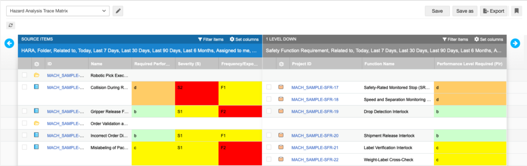
Example of Hazard Analysis Trace Matrix
Companies choose Jama Connect for Industrial Machinery Development to innovate faster and deliver complex, safety-critical machinery with confidence, knowing that every requirement is met, tested, and documented for the global market. To learn more, visit www.jamasoftware.com
“Jama Connect fits our strategy perfectly, serving as a central enabler for structured, traceable, and scalable product development.” – Andreas Spenninger, Head of Industrialization & Safety Manager, Agile Robots SE
Agile Robots Boosts Internal Process Efficiency by Moving to Jama Connect
Agile Robots is a leading provider of next-generation automation solutions. By combining artificial intelligence and robotics, the company makes industries smarter, more flexible, and more efficient.
CUSTOMER STORY OVERVIEW
Agile Robots’ development teams were using three different requirements management tools, which unnecessarily complicated their processes. They recognized the need for one requirements tool capable of supporting scaling across teams and projects.
Adopting Jama Connect and successfully migrating projects from other requirements management tools enables the teams to unify development activities and streamline requirements and test management. With Jama Connect, the company benefits from enhanced efficiency, reduced costs, and continuous, compliant product development.
CHALLENGES
Hindered collaboration due to fragmented toolchain with teams using different requirements management tools
Inefficient requirements management and verification due to need to switch between multiple tools
Risk of miscommunication, rework, and project delays, jeopardizing critical deadlines
Agile Robots’ development teams switching between three requirements management tools, each with unique processes and terminologies, was time-consuming and inconvenient. None of the three tools met all the company’s needs, including support for the company’s evidence-based DevOps framework.
Reduced barriers to collaboration across development teams by unifying processes on one powerful platform
Assured continuity with expert-supported migration of historical project data from three legacy requirements management tools
Integrated test management eliminated need for separate test tools
Demonstrated compliance to regulatory agencies to keep pace with need to develop fast
“Our migration from the previously used requirements management tools has been a complete success. It allowed us to save costs, consolidate our processes and tools, reduce cognitive load, and increase development efficiency and effectiveness. Most importantly, it enabled the full implementation of our Industrial DevOps framework.” – Andreas Spenninger, Head of Industrialization & Safety Manager, Agile Robots SE
EVALUATION
Agile Robots approached the selection of a single requirements management tool from a holistic standpoint, evaluating all available options. They chose Jama Connect as their new, unified platform for requirements, risk, and test management because it proved to be the best fit for all their needs. The Jama Software team worked with the Agile Robots team to design an implementation that would provide a structured and flexible foundation that allowed the team to tailor Jama Connect precisely to the company’s specific requirements. Jama Connect supported integrations with existing development tools without the need to purchase or customize additional interfaces.
Migration of historical project data from three different systems into one cohesive platform that could maintain the integrity and traceability of years of development work Configuration of a single solution, its roles, attributes, and templates to fit the company’s products, processes, and regulatory needs, including safety standards like IEC 61508 and ISO 13849-1 Integration of test case runs with requirements for compliance
“The onboarding process is fast and the software is intuitive, especially with the way we defined our processes and workflows optimizing for rapid development while keeping procedures efficient and diligent to achieve safety and high-quality standards.” – Andreas Spenninger, Head of Industrialization & Safety Manager, Agile Robots SE
OUTCOMES
Improvement in development and certification time
Reduced barriers to collaboration across development teams by unifying processes on one powerful platform
Assured continuity with expert-supported migration of historical project data from three legacy tools
Integrated test management eliminated need for separate test tools
Demonstrated compliance to regulatory agencies to keep pace with need to develop fast
By implementing Jama Connect, Agile Robots created a single, centralized hub for all development activities, eliminating inefficiencies and barriers to collaboration. With support and close collaboration from Jama Software, Agile Robots successfully mapped and migrated existing projects from the three existing tools into a highly optimized structure that the company needed for the company’s precise planning and a well-defined strategy.
Learn how Jama Connect helps industrial companies>/u> succeed with compliance and collaboration.
Jama Connect Features in Five: Surgical Robotics Framework
In this Features in Five session, Máté Hársing – Senior Solutions Architect, explores how Jama Connect’s Surgical Robotics Framework empowers teams to manage the complexity of developing cutting-edge surgical robotic systems while maintaining compliance and accelerating innovation.
Centralized platform for managing user needs, system and subsystem requirements, risks, and verification with seamless navigation and visibility.
Controlled reuse capabilities to manage libraries, variants, and generations, ensuring efficiency without duplication.
Release and generation management tools to baseline requirements for regulatory submissions while enabling innovation for future product generations.
With Jama Connect, surgical robotics teams can streamline development, reduce errors, and bring innovative products to market faster—all while staying audit-ready and compliant.
Hello, I’m Máté Hársing, a Senior Solutions Architect at Jama Software. Surgical Robotic systems are among the most complex medical devices today, combining hardware, software, AI, and strict regulatory demands across multiple generations. In this Features in Five video, I’ll show how Jama Software’s surgical robotics framework helps teams manage that complexity through structured views, variant and release management and end-to-end traceability without sacrificing compliance. Let’s start with the challenges surgical robotics teams face.
Understanding System Complexity
First, system complexity. Multiple subsystems, robotic arms, vision systems, control software, and user interfaces, each developed by different teams but tightly coupled. Second, reuse at scale. Many organizations don’t build just one robot. They build platforms, derivatives, and next-generation systems.
Copying requirements or test cases quickly and manually leads to confusion and risk. Different instruments, markets, and clinical use cases introduce variability that must be controlled, not duplicated. Release and generation management teams need to freeze baselines for regulatory submissions while continuing innovation for the next release or product generation.
Traditional documents and disconnected tools simply don’t scale to this level of complexity.
This is where Jama Connect and the surgical robotics framework come in. The framework provides a pre-structured data model aligned to robotic systems engineering covering user needs, system and subsystem requirements, risks, validation, and verification. On top of that structure, Jama Connect enables controlled reuse in three powerful ways. Libraries to centrally manage shared and reusable assets, variants to model differences without duplicating data, release and generation management using baselines and reuse patterns to support regulatory submissions and future innovation. Together, these capabilities allow teams to scale development without losing control, traceability, or compliance.
Overview of Product Management Scale
Before we look at any libraries, variants, or generations, it’s important to understand the scale of the product we’re managing.
This demo dataset, based on the surgical robotic platform, consists of ten systems: robotic arms, vision, control software, imaging, and safety, broken down into thirty subsystems.
All this lives in a single Jama Connect project organized neatly in the project explorer tree. The project structure mirrors the system architecture, making it easy to navigate from high-level user needs all the way down to detailed subsystem requirements, risks, and verification, without jumping between tools or documents. Despite the complexity, teams can quickly find what they need, understand ownership, and see how everything connects.
Utilizing Hazards Library for Reusability
Here, we use a Hazards Library project to manage reusable content.
These assets are created once and reused across multiple surgical robot programs and generations. When a library item changes, Jama Connect highlights the impact on locations where it’s being reused, allowing teams to review and selectively accept updates, maintaining control while avoiding duplication.
Many organizations manage parallel surgical robot variants that have the same core skeleton of requirements, tests, and risks, but differ in various specific aspects. Using reuse and synchronization, teams can share a common baseline while clearly seeing what’s different in each variant. Jama Connect highlights the delta, what’s been added, changed, or removed, so teams can focus only on what matters. And when needed, changes can be synced in either direction from the core platform to a variant or from a variant back to the platform, always with full visibility and control.
Release and Generation Management Process
Let’s look at release and generation management. For each regulatory submission or product release, we baseline the full set of requirements, risks, and verification. That baseline becomes our approved auditable snapshot. From there, we can reuse that baseline or duplicate and synchronize the entire project to start the next release or product generation, building on what’s already validated while clearly tracking what’s new or changed. This allows teams to move fast without losing control or compliance.
Conclusion and Call to Action
With Jama Software’s surgical robotics framework, teams can handle system complexity with structured end-to-end traceability, reuse safely through governed libraries and variant management, manage multiple releases and generations without chaos, and accelerate development while staying audit-ready and compliant. The result is faster innovation, fewer errors, and greater confidence in both your product and your process. That is a quick look at how Jama Connect helps surgical robotics teams manage complexity through smart views. To learn more about the surgical robotics framework or request a personalized demonstration for your team, visit jamasoftware.com or reach out to your Jama Software customer success manager or solution consultant. Thank you.
This blog recaps our webinar, “Best Practices for Test Management” – Watch it in its entirety HERE.
Transform Your Development Lifecycle with Modern Test Management
Building complex systems demands more than just functionality—it requires precision, compliance, and reliability. Verification and validation are the cornerstones of ensuring your product meets industry standards and exceeds expectations.
Traditional testing methods can’t keep up with the growing demand for faster delivery and uncompromised safety in complex system development. In this session, we’ll look at how adopting a modern test management approach can transform the way you develop and deliver complex systems.
JoinRomer De Los Santos, Principal Solutions Manager at Jama Software, for a deep dive into optimizing your testing lifecycle. We will discuss the critical shift toward requirements-based testing and how connecting test status directly to requirements ensures complete traceability and streamlines development.
What you’ll learn:
Achieve end-to-end traceability by linking test results directly to requirements
Ensure compliance and eliminate gaps in your development process
Empower QA teams to validate requirements early, accelerating approvals
Foster seamless collaboration between engineering and quality assurance teams
Gain real-time visibility into test progress to proactively address roadblocks
Leverage data-driven insights to mitigate risks and enhance product quality
Don’t miss this opportunity to improve how you manage verification and validation.
THE VIDEO BELOW IS A PREVIEW – WATCH THE ENTIRE PRESENTATION HERE
TRANSCRIPT PREVIEW
Romer De Los Santos: Hello, everyone. I’m Romer De Los Santos, a principal solutions consultant here at Jama Software, specializing in software development and process improvement for the medical advice and life sciences vertical. Before joining Jama Software, I spent over 20 years developing a myriad of medical devices, including insulin pumps, continuous glucose sensors, diabetes management software, solid-state cardiac spec cameras, genomic sequencers, and IVD genomic assays. Having served in the roles of software developer, test lead, systems engineer, technical product manager, core team lead, and even a short stint as an internal auditor, I have gained firsthand experience in the full development lifecycle and have an understanding of the perspectives of the different stakeholders involved in development. I’m pleased to be here today to present on test management using Jama Connect®.
Jama Connect is a highly configurable requirements management tool that includes robust test management capabilities. I’m happy to share some best practices on how to use those capabilities. This is not intended to be a step-by-step tutorial on how to perform testing using Jama Connect. Instead, I’ll be going over some testing concepts and best practices to help improve your experience with the tool. Then I’ll provide some information on what is possible and how you can extend Jama Connect’s capabilities. First, let’s start with a discussion about the structures around testing in Jama Connect, and how understanding those structures will help you manage your testing effort.
The scope of testing is defined by a test plan, and test execution must be in the context of a test plan. Many users use one test plan per release. However, for more complex projects, it may make more sense to break up testing into one test plan per major component or one test plan per test team. Having a test plan per component allows you to leverage the testing of that component whenever the component is used. Having a test plan per test team allows individual test teams to manage their own testing effort independently, and is often used by very large organizations. Your testing strategy depends on your situation, and if you need advice, please contact your designated Jama Solutions consultant or your customer success manager.
Test plans contain groups of test cases. Jama Connect adds test cases to a cycle of testing by test group and status. The criteria you use for grouping test cases is up to you; however, it is best practice to organize test groups by functional group, which is defined as a feature or functionality that can be independently tested. This type of organization facilitates reuse. For example, say you swap out an imaging module for a genomic sequencer with an equivalent component. Instead of cherry-picking individual test cases, you can rerun the imaging module test group. Now, let’s talk about the structures around test execution.
De Los Santos: A group of test runs is known as a test cycle. Jama Connect will allow you to add to the test cycle by test group, test status, pass or fail, and will even give you the option of cherry-picking from the selected test groups. Test cycles can be run in series or in parallel. If you have a small team, you may choose to run one cycle at a time. If you have multiple test teams, it may be more efficient to have each test team have their own test cycles so that testing can be run in parallel. When running multiple test cycles in parallel, it is best practice to agree on a naming convention to minimize ambiguity when looking at a growing list of test cases. Something like Alpha Team Cycle 1 identifies the team and the current cycle they’re on.
Each test case added to the test cycle will spawn a test run, which captures the execution of the test case. The test run is synchronized with the version of the test case at the time the test cycle was created. If there are any changes after that point, the test run will not automatically update until you choose to resynchronize them. However, doing so will wipe out any progress you’ve currently made on your test run. If you want to keep your progress and continue your work on your previous test case, then don’t sync. Jama Connect allows you to run different versions of the same test case, as long as they live in different test cycles.
Now, this is a good time to talk about the concept of parameterization. Parameterization is when a single test case is run multiple times to verify a specific set of parameters. It’s best practice to duplicate the test case for each parameter so that you have a separate test run per parameter. While this method does increase the total number of test cases in your test plan, it also ensures that each parameter is tested and captured in its own test run, thus eliminating ambiguity in your testing results.
Since Jama Connect is an item-based software solution, you can use item locks to manage your testing effort. If you lock a test plan, you prevent modifications to the test plan, the adding and removing of test cases and the organization of those test cases into test groups. However, testers are still able to create test cycles and execute test runs. They can also choose to synchronize runs to the latest versions of your test cases. In other words, when locking a test plan, you have control over what test cases are run and how they are organized. If you choose to lock a test cycle, you will ensure that testers execute the version of the test case at the time the cycle was created or last synchronized. Thus, locking the test cycle gives you control over the version of the test case to be executed. Finally, if you want to prevent a test case from being run, you should lock the associated test run. This effectively prevents any test execution.
De Los Santos: While Jama Connect is not designed as a dedicated test management tool, it can be configured to be compatible with most testing processes. Let’s go over some of the most useful configuration options available to you. What I’m showing you here is Test Center in Jama Connect. One of the most common requests I receive from my clients is, ” Where can I put a prerequisite or preconditions field in Jama Connect?” Ideally, you want to place it where the description field is located on the test execution tab here. However, you don’t have control over the order of the items that are going to be displayed on the test execution tab.
The best way to accomplish this is to reuse or rather commandeer the description field of your test case to be your new preconditions field. So the way you would do that very simply is you would go to your admin panel, go to item types, select your particular test case item, and then look for a unique field name called description and rename that to be your preconditions field. Any value you enter into your new preconditions field will appear in the description field of the associated test run. All right? So let’s try it out. Let’s go into our project, go under verifications. We’ll pick the first test case and enter a precondition for a prerequisite. This is a precondition. Save that off. When we go back to the test plan and look at the test runs, you’ll notice it’s now out of sync because we updated the test case. We’ll go ahead and resync, and now, when you execute your particular test case, or rather, execute the test run, you’ll see here that the precondition now appears above the test steps.
A functional safety assessor selects one hazard from the risk file and asks a fault-tree question. Which combinations of failures could produce this event, and how probable is the worst case? Afailure mode inventory for risk supplies the basic events. Fault Tree Analysis (FTA), sometimes referred to as tree fault or failure tree analysis, models how individually harmless faults can combine to produce a catastrophic outcome. We’ve watched this gap surface late in programs we’ve worked with, when reworking a redundancy scheme costs months instead of days during architecture design.
This guide covers how fault trees are built, how the same logic applies to mechanical and software failures, and how to keep cut sets tied to requirements and tests throughout every audit.
What Is Fault Tree Analysis (FTA)?
In FTA, analysts start from one defined undesired outcome, called the top event, and work backward through every combination of causes that could produce it. The method identifies causes, or combinations of causes, that can lead to the defined top event, which is how the International Electrotechnical Commission (IEC) 61025 defines the method. That direction of reasoning separates fault trees from inductive methods like Failure Mode and Effects Analysis (FMEA), which start from individual component failures and reason forward to their effects. We commonly use IEC 61025 as the reference for FTA symbols, gates, and analysis approaches, while domain safety handbooks and sector-specific practices supply additional methodology.
Where Fault Tree Analysis Pays Off
The real payoff shows up in combinations a single-failure review never surfaces. Bottom-up methods catch the failure modes analysts already expect. A fault tree forces the same analysts to ask which combinations of ordinary failures add up to the one outcome nobody can tolerate, and that reframing routinely turns up a shared component sitting under two branches that were supposed to be independent.
The same tree also produces the math a functional safety case needs. Once basic events carry reliability data, Boolean reduction turns the diagram into minimal cut sets ranked by probability, which is how a program demonstrates it meets a quantitative target, such as the FAA’s catastrophic-failure threshold, rather than asserting the architecture is safe.
That documented chain of reasoning is what holds up under audit. A completed fault tree shows an assessor exactly which single points of failure the design still carries and which redundancies share a hidden weakness, in a form a reviewer can trace rather than take on faith.
When Fault Tree Analysis Is Worth the Effort
Not every failure mode needs a full fault tree, and building one for a low-consequence issue burns time the analysis doesn’t repay. The method earns its keep on a narrower set of situations:
Catastrophic top events: the failure could hurt someone or damage the environment, and the team needs every path to that outcome mapped, not just the obvious ones.
Redundancy and common-cause risk: the architecture leans on backup systems, and the analysis needs to confirm those backups don’t secretly share a single weakness.
Regulatory or certification targets: the program must demonstrate a quantitative probability target, and a fault tree is the artifact that shows the math behind the claim.
Outside those cases, a lighter method such as FMEA usually gets the team to the same design decisions faster.
How to conduct FTA
Building a fault tree starts by defining the top event and connecting contributing events with Boolean logic gates. Each branch should stay tied to the failure question so the tree does not become a catalog of every possible defect.
Start by Defining the Top Event
The analysis starts with the one failure that absolutely can’t happen, such as unintended braking or loss of thrust. Getting the scope right is an engineering judgment. Being too general becomes unmanageable, and being too specific misses the broader failure picture. Complex systems often have several fault trees, one per top event, particularly for missions with distinct hazard phases. We use that boundary to keep each tree focused on the failure combination it must explain and the hazard the team needs to control.
Map Intermediate and Basic Events
From the top event, we ask what could cause it, then repeat that question at each level down. Intermediate events, drawn as rectangles, occur because of other events. Basic events, drawn as circles, are the initiating faults that need no further development, typically a component failure with known reliability data.
An undeveloped event, drawn as a diamond, marks a fault we chose not to expand, either insufficiently consequential or lacking data. Analysts should mark those boundaries explicitly, since a fault tree can never guarantee completeness, and a probability computed from an incomplete tree can be unconservative, exactly the hidden assumption an assessor will challenge.
Connect Events With Logic Gates
Gates define how lower-level events combine. An AND gate (all of its inputs must occur before it fires) is how redundancy shows up in a tree, while an OR gate (any single input is enough to fire it) covers the alternative case. Specialized gates cover other structures. The inhibit gate passes an input only under a conditioning event, the voting gates model k-out-of-n redundancy, and the priority AND gate requires inputs in sequence.
The finished tree gives us more than a diagram, since Boolean reduction of the gate logic produces minimal cut sets, the smallest combinations of basic events causing the top event. A one-component cut set is a single point of failure, while two-component cut sets are double failures that defeat a redundancy. With reliability data, the tree also supports quantitative analysis of the top event’s probability.
Catastrophic transport-aircraft failure conditions must meetcatastrophic failure probability targets of no more than 1 × 10⁻⁹ per flight hour under Federal Aviation Administration (FAA) system safety assessment expectations. Fault trees commonly demonstrate an architecture that reaches the target.
How an FTA Exposes Hidden Failure Combinations: 3 Examples
The same logic applies to mechanical systems, software-related failures, and redundant safety architectures, and a sample fault tree from each domain shows how seemingly independent faults prove coupled.
Try the Method on a Mechanical System
A mechanical fault tree can use motor overheating as the top event. An OR gate splits it into a motor malfunction, a basic event, and excessive current reaching the motor, which needs development. Excessive current sits under an AND gate, requiring current in the circuit and a fuse that fails closed.
The circuit overcurrent splits under an OR gate into a wiring short, a basic event, and a voltage surge, left as an undeveloped diamond. The analysis yields a two-component minimal cut set, the fuse fails closed and the wiring shorts. A failed fuse in a healthy circuit does nothing, and a short with a working fuse gets interrupted, but together they overheat the motor.
That combination is what a bottom-up, one-failure-at-a-time analysis tends to miss, and fault trees also expose common cause failures this way. In a redundant fire pump system with no water as the top event, the same basic event, engine failure, appearing under both pump branches of an AND gate shows one shared engine quietly cancels the redundancy.
Apply the Same Logic to Software-Related Failure
When the failure runs through the software, the logic holds, but the arithmetic changes. In an infusion pump, unintended drug overdose can be the top event. An AND gate splits it into two conditions that must occur together: a hazardous over-delivery condition and a failure of the detection path meant to catch it before it reaches the patient. The over-delivery condition sits under its own AND gate, where the valve sticks open, and the flow sensor gives a false reading. The detection failure sits under an OR gate, where any single alarm failure lets an over-delivery underway go unnoticed.
Over-delivery alone requires two coincident hardware faults, and a software-related alarm failure can’t cause an overdose by itself. It can only defeat detection once over-delivery has started, which is why the top event needs both branches together, not either one alone. For software basic events, we avoid treating them like hardware failure rates unless the applicable standard and evidence support that choice. Medical device and automotive programs commonly separate software faults, introduced through specification or implementation, from randomly occurring hardware faults, so the two kinds of reliability reasoning stay distinct.
Extend the Analysis to a Redundant Safety System
Consider an aircraft brake system, where the top event is complete loss of braking on landing. An AND gate splits it into two parallel hydraulic systems failing together, since either system alone can stop the aircraft.
Each hydraulic branch fails through an OR gate covering a pump failure, a basic event, or a line rupture, another basic event. Taken alone, that yields no single point of failure, since both branches would have to fail independently for the top event to occur.
The tree earns its place when the two branches share a reservoir or a single pump drives both circuits under normal load. That shared basic event under both AND-gate inputs turns two supposedly independent systems into one common-cause failure, the same pattern a bottom-up review of each branch in isolation would miss.
Differences between FTA and FMEA
FTA and FMEA differ in four practical ways:
Aspect
Fault Tree Analysis
FMEA
Direction
Deductive, top-down
Inductive, bottom-up
Starting point
One undesired top event
Individual component failure modes
Failure scope
Combinations of failures
Generally, single points of failure
Output
Graphical tree with minimal cut sets
Tabular worksheet with Risk Priority Number (RPN) ranking
FTA models combinations of failures, traces common cause failures across subsystems, and can support a quantitative functional-safety target. FMEA fits earlier in design, when changes are cheapest, and the inventory is still being built.
For regulated programs, domain practice often settles the question.Aircraft safety assessment practice uses both, with lower-level failure-mode data feeding system-level fault trees. As Automotive Safety Integrity Level (ASIL) criticality increases, automotive programs often pair inductive and deductive analyses, drawing on our breakdown ofautomotive ASIL safety levels, whilemedical device risk analysis under ISO 14971 may also need to weigh sequences and combinations of events that an FMEA alone may not capture.
How to Build an FTA Template Auditors Can Follow
A useful FTA analysis template documents the decisions that make the diagram defensible under audit, especially when a reviewer asks why a branch stopped or a cut set led to a requirement.
Capture the FTA Decisions Behind the Diagram
A working FTA template captures the core decisions behind the tree, and these entries keep the assumptions, boundaries, input data, and results reviewable:
Scope and problem statement: The system, its boundaries, and what the analysis decides.
Top event statement: A precise undesired outcome, such as a pump failing to deliver flow, is drawn as the tree’s root.
Assumptions and boundary conditions: Operating conditions, exclusions, and failure modes considered.
Event hierarchy with gate logic: Every intermediate event is connected through a defined gate, down to basic and undeveloped events.
Basic event data: Failure rates from equipment databases, manufacturer specifications, field history, or reliability handbooks.
Cut set analysis: Minimal cut sets ranked by probability, with single-event cut sets flagged as single points of failure.
Documentation and reporting: The reliability-target status and dominant contributing failure modes, with design comparisons where needed.
Audit problems often arise when a single-point failure’s derived requirement moves into another system, and the connection back to the hazard decays until an auditor pulls a sample. Keeping that requirement linked to its original top event and verification test, and flagging both the moment the hazard or mitigation changes, is what keeps the chain current as the design evolves.
Keep Symbols and Software Practical
A typical template should leave room for the standard FTA symbol set, covering basic, intermediate, and undeveloped events, house events, conditioning ellipses, and page-transfer triangles (the FAQ below breaks each down). Dedicated FTA software builds and quantifies fault trees and derives cut sets, with commercial and open-source options covering common cause modeling and Monte Carlo uncertainty analysis.
Automation is advancing on two fronts, but it still needs engineering judgment. Model-based safety analysis workflows can help generate fault trees and analyze cut sets from system models, and published approaches now uselarge language model approaches to suggest sub-causes while the human analyst leads the analysis.
Where Fault Tree Analysis Falls Short
A fault tree only models binary states. A component either works or it has failed, which means the method struggles with partial degradation and doesn’t capture the order events happen in, only which combinations occur. Complex systems can produce trees with hundreds of gates that become difficult to maintain as the design changes.
The bigger limitation shows up after the diagram is finished. A cut set identifies a single point of failure, but the mitigation requirement written against it often lives in a different system than the tree itself, and the link between them fades once the program moves past the safety review.
That gap turns a defensible piece of analysis into a static document nobody trusts by the next audit. The tree itself isn’t the weak point. What breaks down is the connection between the tree, the mitigation, and the test that’s supposed to prove it worked.
How Jama Connect Supports Fault Tree Analysis
Dedicated FTA tools draw fault trees. Jama Connect® can keep FTA outputs, such as top events, cut sets, and derived mitigations, connected to requirements and tests, and itsLive Traceability™ flags a downstream requirement or test case as suspect the moment an upstream hazard or mitigation changes.
Jama Connect’s risk management capabilities support Preliminary Hazard Analysis (PHA) and FMEA aligned with ISO 14971 and IEC 60812. That means the failure mode inventory that populates fault tree basic events can live alongside the requirements it traces to, and a change to any requirement flags linked risk records and test cases for review. For teams running fault trees in a separate environment, linking or importing key FTA outputs into Jama Connect can help keep records from drifting apart.
How to Turn Fault Tree Findings Into Traceable Action
A practical first fault tree covers one top event developed to the limit of your reliability data. The cut sets it produces become a work list, covering single points of failure to redesign, double-failure combinations to monitor, and mitigations to write as requirements.
Jama Connect can keep those cut sets, the mitigations tied to them, and the verification tests connected as the design evolves, with results captured on the platform. If your next audit depends on that proof,start a free 30-day trial and see the workflow.
Frequently Asked Questions About Fault Tree Analysis
What is the difference between FTA and an FMEA?
They are complementary analyses that approach the same risk from opposite ends. FMEA provides component-level failure-mode data that populates basic events in fault trees, while FTA shows which combinations matter for the top event. Teams already running FMEA can reuse that data as a starting point rather than rebuilding it, a workflow that ourguide to performing FMEA covers. Keeping both analyses tied to the same risk records in Jama Connect makes that reuse concrete.
What symbols are used in a fault tree diagram?
Circles represent basic events, rectangles represent intermediate events, and diamonds mark undeveloped events. The house shape marks external events that aren’t faults, ellipses record conditioning events, and triangles transfer branches between pages. Gates include AND, OR, inhibit, voting, exclusive OR, and priority AND, matching the team’s standard, tool, and reviewer. Consistency matters more than completeness. A small, consistent symbol set holds up better under audit than borrowed conventions.
Can FTA be automated?
Parts of it can be automated. Model-based safety analysis tools can generate fault trees, derive minimal cut sets, and calculate failure rates from system models, though automated generation still depends on the quality of the failure-mode model. Current AI approaches position large language models as co-pilots that suggest sub-causes while the analyst leads. Whichever tool generates the sub-causes, the result still has to trace back to a real requirement and test to hold up under audit, where Jama Connect’s traceability matters more than the tree-drawing itself.
When in the development lifecycle should FTA be performed?
FTA should be performed early in design and again whenever the system changes. Aerospace teams may use fault trees during early architecture assessment to derive safety requirements, then again to check the implemented design, a pattern theclassic V-model development lifecycle mirrors. Early trees shape the architecture, and later trees confirm the built system meets the target. Functional safety teams generally reassess the tree whenever the architecture, hazards, mitigations, or reliability data change.